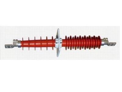
Introduction
10-35kV Composite Coating Purely Dry Wall Bushing of Capacitor Type is mainly used in indoor transformer station, which will serve as transition carrier for electric insulation and mechanical support when HV heavy current passes through wall or other grounding bodies.
The serial composite coating dry wall bushing adopts new composite mateials and manufacturing process and technology, with once-pressing forming, special design, simple strcture, strong integrity and excellent property. The products can reach “maintenance—free” requirment by Power Department.
Characteristics
composite coating purely dry wall bushing meets all provisions of GB4109 , IEC60137 and has following characteristics:
Full—sealed dry structure, completely avoiding the danger of oil leakage, air leakage and explosion;
Simple structure, small volume, light weight, hard to be damaged and easily transported and mounted;
The main insulation of the product adopts new-type composite insulating materials imported from USA and the capacitor screen of core adopts new-type semiconductor material, which improves the voltage distribution of ends of pole plates, decreases discharge inception voltage, and establishes firm foundation for the promotion of stability of electric property.
As this product is composed of “purely” dry composite materials, without oil, gas (SF6) or any pollution to environment during production and operation. It is an environment-friendly “green” HV electric prduct.
Adopting silicon rubber composite coating and designed according to above anti-pollution Class Ⅲ, with high anti-pollution and completely meets the operating requirements in the seriously- polluted region;
The whole product is purely dry and usese solid materials with tight structure. Its mechanical strength is four times that of ordinary steel bar. Its electric and mechanical property is steady and reliable with long service life. So the product realizes “maintenance-free” requirement proposed by Power Department.
Overall Dimension
|
Model |
Length (L) mm |
Length of Indoor End (L1) mm |
Flange Length of Indoor End (L2) mm |
Insulation Distance of Indoor End (L3) mm |
Insulation Distance of Outdoor End (L4) mm |
Flange Thickness (L5) mm |
Dia. of Umbrella of Outdoor End (D1) mm |
Dia. of Holes of flange mounting (D2) mm |
Dia. of Umbrella of Indoor End (D3) mm |
No. of Holes of Fange Mounting n1--d1 |
Pitch of Holes of Connection Terminal a mm |
No. of Holesof Connection Terminal n--d |
Weight |
|
FCGWL-40.5/400 |
1270 |
615 |
30 |
390 |
415 |
15 |
175 |
□200 |
164 |
4-ф14 |
40*40 |
4-ф18 |
19 |
|
FCGW-40.5/800 |
1270 |
615 |
30 |
390 |
415 |
15 |
175 |
164 |
19 | ||||
|
FGW-24/400 |
420 |
420 |
30 |
360 |
400 |
15 |
172 |
152 |
12 | ||||
|
FGW-24/800 |
420 |
420 |
30 |
360 |
400 |
15 |
172 |
152 |
12 | ||||
|
FGW-12/400 |
790 |
380 |
30 |
200 |
210 |
15 |
172 |
152 |
10 | ||||
|
FGW-12/800 |
790 |
380 |
30 |
200 |
210 |
15 |
172 |
152 |
10 |
|
Model |
Rated Voltage |
Max. Operating Voltage |
Rated Current |
60s Power Frequency Withstand kV |
Lightning Impulse Withstand kV |
Permitted Bending Load N |
Dielectric Loss Angle Tangent % |
Dielectric Loss Angle Tangent % |
|
FCGWL-40.5/400 |
40.5 |
23 |
400 |
95 |
200 |
500 |
>0.7 |
>10 |
|
FCGW-40.5/800 |
40.5 |
23 |
800 |
95 |
200 |
500 |
>0.7 |
>10 |
|
FGW-24/400 |
24 |
14 |
400 |
58 |
125 |
1000 |
/ |
/ |
|
FGW-24/800 |
24 |
14 |
800 |
58 |
125 |
1000 |
/ |
/ |
|
FGW-12/400 |
12 |
7 |
400 |
42 |
75 |
700 |
/ |
/ |
|
FGW-12/800 |
12 |
7 |
800 |
42 |
75 |
700 |
/ |
/ |


